
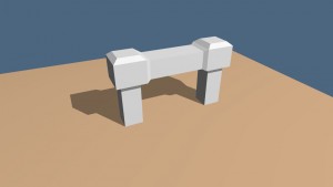
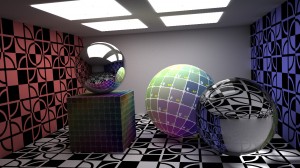
In this post we will expand on our skybox project by adding an object to our scene for which we will evaluate lighting contributions and environment mapping. We will first make a quick edit to our Wavefront OBJ loader to utilize OpenGL's Vertex Buffer Object. Once we can render an object we will create a shader program to evaluate the lighting and reflections. Below are a couple of screen grabs of the final result.


A couple of video captures are below.
The relevant modifications to our Wavefront OBJ loader are below. These methods expect normals to be specified in the obj file in addition to the faces being rendered with triangles. The setupBufferObjects method is just a quick way to load our vertices and normals into a Vertex Buffer Object once our OpenGL context has been created. We've defined a structure, v, padded to 32 bits, to store our data. We have a render method to render our model. Note that we have specified an offset for the normals using the glVertexAttribPointer function.
struct v {
	GLfloat x, y, z;
	GLfloat nx, ny, nz;
	GLfloat padding[2];
};

void cObj::setupBufferObjects() {
	int size = faces.size();
	v *vertices_ = new v[size*3];
	unsigned int *indices_ = new unsigned int[size*3];
	for (int j = 0, i = 0; i < size; i++) {
		vertices_[j].x  = vertices[faces[i].vertex[0]].v[0];
		vertices_[j].y  = vertices[faces[i].vertex[0]].v[1];
		vertices_[j].z  = vertices[faces[i].vertex[0]].v[2];
		vertices_[j].nx = normals[faces[i].normal[0]].v[0];
		vertices_[j].ny = normals[faces[i].normal[0]].v[1];
		vertices_[j].nz = normals[faces[i].normal[0]].v[2];
		indices_[j]     = j;
		j++;

		vertices_[j].x  = vertices[faces[i].vertex[1]].v[0];
		vertices_[j].y  = vertices[faces[i].vertex[1]].v[1];
		vertices_[j].z  = vertices[faces[i].vertex[1]].v[2];
		vertices_[j].nx = normals[faces[i].normal[1]].v[0];
		vertices_[j].ny = normals[faces[i].normal[1]].v[1];
		vertices_[j].nz = normals[faces[i].normal[1]].v[2];
		indices_[j]     = j;
		j++;

		vertices_[j].x  = vertices[faces[i].vertex[2]].v[0];
		vertices_[j].y  = vertices[faces[i].vertex[2]].v[1];
		vertices_[j].z  = vertices[faces[i].vertex[2]].v[2];
		vertices_[j].nx = normals[faces[i].normal[2]].v[0];
		vertices_[j].ny = normals[faces[i].normal[2]].v[1];
		vertices_[j].nz = normals[faces[i].normal[2]].v[2];
		indices_[j]     = j;
		j++;
	}

	glGenBuffers(1, &vbo_vertices);
	glBindBuffer(GL_ARRAY_BUFFER, vbo_vertices);
	glBufferData(GL_ARRAY_BUFFER, size*3*sizeof(v), vertices_, GL_STATIC_DRAW);

	glGenBuffers(1, &vbo_indices);
	glBindBuffer(GL_ELEMENT_ARRAY_BUFFER, vbo_indices);
	glBufferData(GL_ELEMENT_ARRAY_BUFFER, size*3*sizeof(unsigned int), indices_, GL_STATIC_DRAW);

	delete [] vertices_;
	delete [] indices_;
}

void cObj::render(GLint vertex, GLint normal) {
	glBindBuffer(GL_ARRAY_BUFFER, vbo_vertices);
	glEnableVertexAttribArray(vertex);
	glVertexAttribPointer(vertex, 3, GL_FLOAT, GL_FALSE, sizeof(v), 0);
	glEnableVertexAttribArray(normal);
	glVertexAttribPointer(normal, 3, GL_FLOAT, GL_FALSE, sizeof(v), (char *)NULL + 12);
	glBindBuffer(GL_ELEMENT_ARRAY_BUFFER, vbo_indices);
	glDrawElements(GL_TRIANGLES, faces.size()*3, GL_UNSIGNED_INT, 0);
}

void cObj::releaseBufferObjects() {
	glDeleteBuffers(1, &vbo_indices);
	glDeleteBuffers(1, &vbo_vertices);
}
We have also create a function, createProgram, to create our shader program which we discussed in the previous post on rendering a skybox.
void createProgram(GLuint& glProgram, GLuint& glShaderV, GLuint& glShaderF, const char* vertex_shader, const char* fragment_shader) {
	glShaderV = glCreateShader(GL_VERTEX_SHADER);
	glShaderF = glCreateShader(GL_FRAGMENT_SHADER);
	const GLchar* vShaderSource = loadFile(vertex_shader);
	const GLchar* fShaderSource = loadFile(fragment_shader);
	glShaderSource(glShaderV, 1, &vShaderSource, NULL);
	glShaderSource(glShaderF, 1, &fShaderSource, NULL);
	delete [] vShaderSource;
	delete [] fShaderSource;
	glCompileShader(glShaderV);
	glCompileShader(glShaderF);
	glProgram = glCreateProgram();
	glAttachShader(glProgram, glShaderV);
	glAttachShader(glProgram, glShaderF);
	glLinkProgram(glProgram);
	glUseProgram(glProgram);

	int  vlength,    flength,    plength;
	char vlog[2048], flog[2048], plog[2048];
	glGetShaderInfoLog(glShaderV, 2048, &vlength, vlog);
	glGetShaderInfoLog(glShaderF, 2048, &flength, flog);
	glGetProgramInfoLog(glProgram, 2048, &flength, plog);
	std::cout << vlog << std::endl << std::endl << flog << std::endl << std::endl << plog << std::endl << std::endl;
}
Now we can discuss our lighting model. Our lighting model will be the sum of four contributions, emissive, ambient, diffuse, and specular.
\begin{align}
\vec{color_{final}} &= \vec{color_{emissive}} + \vec{color_{ambient}} + \vec{color_{diffuse}} + \vec{color_{specular}}\\
\end{align}
The emissive color is simply the color emitted by our object.
\begin{align}
\vec{color_{emissive}} &= \vec{emissive_{color}} \cdot emissive_{contribution}\\
\end{align}
The ambient term is independent of the location of the light source, but does depend on the object's materials. Think of the material as reflecting ambient light. If our light source is white and the object is green, clearly it should only reflect the green portion of the light spectrum.
\begin{align}
\vec{color_{ambient}} &= \vec{material_{ambient}} \circ \vec{ambient_{color}} \cdot ambient_{contribution}\\
\end{align}
The diffuse term depends on the object's materials, the color of the diffuse light, and also the location of the light source. We will have two vectors at the location we are evaluating, a normal vector and a vector towards the light source. We will use the inner product of these two vectors.
\begin{align}
\vec{a} \cdot \vec{b} &= |\vec{a}||\vec{b}|\cos{\theta}\\
\end{align}
If both vectors are of unit length, we have,
\begin{align}
\vec{a} \cdot \vec{b} &= \cos{\theta}\\
\end{align}
where \(\cos{\theta}\) will range from \([-1,1]\). We are not interested in values less than \(0\) because this would indicate an angle between the normal and light vector of more than \(\frac{\pi}{2}\) radians. When the vectors are parallel and have the same direction, we have a maximum contribution of \(1\) for the diffuse light. For the normal, \(\vec{n}\), and the light vector, \(\vec{l}\), we have,
\begin{align}
\vec{color_{diffuse}} &= \vec{material_{diffuse}} \circ \vec{diffuse_{color}} \cdot \max{(\hat{n} \cdot \hat{l},0)} \cdot diffuse_{contribution}\\
\end{align}
The final specular term depends on the object's materials, the color of the specular light, the location of the light source, and also the location of the viewer. We will implement the Blinn-Phong Shading Model. To do this we need to evaluate the halfway vector between the light vector, \(\vec{l}\), and the vector towards the viewing position, \(\vec{v}\),
\begin{align}
\hat{h} &= \frac{\hat{l}+\hat{v}}{|\hat{l}+\hat{v}|}\\
\end{align}
provided \(|\hat{l}+\hat{v}| \ne 0\). The dot product evaluated for the diffuse contribution indicates whether we apply a specular reflection. If that dot product is greater than \(0\), we evaluate the specular contribution,
\begin{align}
\vec{color_{specular}} &= \vec{material_{specular}} \circ \vec{specular_{color}} \cdot (\hat{n} \cdot \hat{h})^\alpha \cdot specular_{contribution}\\
\end{align}
where \(\alpha\) is the shininess constant.
Before we delve into our shader program, we need to discuss something related to coordinate spaces. Our lighting calculations require all of our vectors and vertices to exist in the same coordinate space. We will pass our model, view, and projection matrices to our shader, and use the model and view matrices to transform our coordinates into eye space. However, due to the nature of nonuniform scaling, applying the model and view matrices to our normals may yield vectors that are no longer normal to the surface. We will instead use the inverse of the transpose of the model view matrix as described below.
For our tangent, \(\vec{t}\), and normal, \(\vec{n}\), and transformed \(\vec{t'}\) and \(\vec{n'}\), all with homogeneous coordinate \(0\), we have,
\begin{align}
\vec{t} \cdot \vec{n} &= 0\\
\vec{t'} \cdot \vec{n'} &= 0\\
\end{align}
so if \(\mathbf{M}\) is our model view matrix and \(\mathbf{N}\) is the matrix we are seeking to transform our normals, we have,
\begin{align}
(\mathbf{M}\vec{t})\cdot(\mathbf{N}\vec{n}) &= 0\\
(\mathbf{M}\vec{t})^T(\mathbf{N}\vec{n}) &= 0\\
\vec{t}^T\mathbf{M}^T\mathbf{N}\vec{n} &= 0\\
\end{align}
and if \(\mathbf{M}^T\mathbf{N} = \mathbf{I}\), we have,
\begin{align}
\vec{t}^T\mathbf{M}^T\mathbf{N}\vec{n} &= 0\\
\vec{t}^T\mathbf{I}\vec{n} &= 0\\
\vec{t}^T\vec{n} &= 0\\
\end{align}
thus,
\begin{align}
\mathbf{M}^T\mathbf{N} &= \mathbf{I}\\
\mathbf{N} &= (\mathbf{M}^T)^{-1}\\
\end{align}
So when transforming normals, we will use the inverse of the transpose of the model view matrix. Let's have a look at our shader. Our vertex shader will accept a vertex and the normal in addition to our light position and projection, view, and model matrices. It will pass the light vector, normal vector, halfway vector, and texture coordinate to the fragment shader. Note that our texture coordinate has three coordinates for sampling from our cube map for environment mapping. In our vertex shader we first transform the incoming vertex; we also transform that vertex into eye space. Our light position uniform is already specified in model space, so we simply apply the view matrix to move it to eye space. We evaluate the light vector as the vector from the vertex to the light source in addition to the normal and halfway vectors using the equations above. We transform our normal vector to model space to get our texture coordinates.
#version 330

in vec3 vertex;
in vec3 normal;
uniform vec3 light_position;
uniform mat4 Projection;
uniform mat4 View;
uniform mat4 Model;
out vec3 light_vector;
out vec3 normal_vector;
out vec3 halfway_vector;
out vec3 texture_coord;

void main() {
	gl_Position = Projection * View * Model * vec4(vertex, 1.0);

	vec4 v = View * Model * vec4(vertex, 1.0);
	vec3 normal1 = normalize(normal);

	light_vector = normalize((View * vec4(light_position, 1.0)).xyz - v.xyz);
	normal_vector = (inverse(transpose(View * Model)) * vec4(normal1, 0.0)).xyz;
	texture_coord = (inverse(transpose(Model))        * vec4(normal1, 0.0)).xyz;
	halfway_vector = light_vector + normalize(-v.xyz);
}
Our fragment shader accepts the normal, light, and halfway vectors in addition to the texture coordinates and cube map. We sample the cube map to get the object's material property and specify colors and contributions for the emissive, ambient, diffuse, and specular components. Lastly, we apply our lighting equations from above to output a fragment color. Note that our colors and contributions are built into our shader. We could have specified these as uniforms to make our shader a bit more configurable.
#version 330

in vec3 normal_vector;
in vec3 light_vector;
in vec3 halfway_vector;
in vec3 texture_coord;
uniform samplerCube cubemap;
out vec4 fragColor;

void main (void) {
	vec3 normal1         = normalize(normal_vector);
	vec3 light_vector1   = normalize(light_vector);
	vec3 halfway_vector1 = normalize(halfway_vector);

	vec4 c = texture(cubemap, texture_coord);

	vec4 emissive_color = vec4(0.0, 1.0, 0.0, 1.0); // green
	vec4 ambient_color  = vec4(1.0, 1.0, 1.0, 1.0); // white
	vec4 diffuse_color  = vec4(1.0, 1.0, 1.0, 1.0); // white
	vec4 specular_color = vec4(0.0, 0.0, 1.0, 1.0); // blue

	float emissive_contribution = 0.02;
	float ambient_contribution  = 0.20;
	float diffuse_contribution  = 0.40;
	float specular_contribution = 0.38;

	float d = dot(normal1, light_vector1);
	bool facing = d > 0.0;

	fragColor =	emissive_color * emissive_contribution +
			ambient_color  * ambient_contribution  * c +
			diffuse_color  * diffuse_contribution  * c * max(d, 0) +
			(facing ?
				specular_color * specular_contribution * c * pow(dot(normal1, halfway_vector1), 80.0) :
				vec4(0.0, 0.0, 0.0, 0.0));
	fragColor.a = 1.0;
}
This shader program yields some nice results, but it only supports one light source and is not very configurable. If we spent some more time, we could create a shader that supports multiple light sources with configurable properties for each source.
Download this project: teapot.tar.bz2
Comments
Hi Keith! I'm not sure but I think I may have found small text errors. Press Ctrl + F and search for "came" and after that "transpose". By "came" you probably meant "same? And by "transpose" you probably meant "transformed"?
Because first you wrote "...use the inverse of the transpose of the model view matrix..." and in a later sentence you wrote "...we will use the inverse of the transform of the model view matrix.". Still I'm not sure but I just wanted to point that out for now anyway 🙂
Thanks for the tutorial. I'm trying to understand it now.
Author
Thanks for the heads up. I've fixed it. It should be "transpose" in the second case. Both sentences should reference ".. the inverse of the transpose of ..".
Alright thanks 🙂
Hey could you help me convert the shaders in glsl 1.20 specification ?
Author
Hey Poornima..
I'm a bit rusty at the moment, but if you want to paste them in here, I'll have a peek.
Another question about both the skybox tutorial and this one. Why are there so many .tga-capturings in the folder? From what I have seen and tested those are not needed to run the program.
Author
You're right. They aren't required.. the 'g' and 'v' keys grab a frame and a sequence of frames, respectively. You can disable those in the
SDL_PollEventloop.Hello Keith! I'm new to linux. I've downloaded your source code and configured all the required lib and package in my vm linux. After typing 'make -f Makefile' in CLI, all went well and file 'main' was created in 'bin'. However, I ran the 'main' in CLI and it threw something that I could't recognize. Text truncated is as follows:
Name: media/dragon_smooth.obj
Vertices: 0
Parameters: 0
Texture Coordinates: 0
Normals: 0
Faces: 0
2.1 Mesa 10.1.3
1.20
1.10.0
GL_ARB_multisample GL_EXT_abgr GL_EXT_bgra GL_EXT_blend_color GL_EXT_blend_minmax GL_EXT_blend_subtract GL_EXT_copy_texture GL_EXT_polygon_offset GL_EXT_subtexture GL_EXT_texture_object GL_EXT_vertex_array GL_EXT_compiled_vertex_array GL_EXT_texture GL_EXT_texture3D GL_IBM_rasterpos_clip GL_ARB_point_parameters GL_EXT_draw_range_elements GL_EXT_packed_pixels GL_EXT_point_parameters GL_EXT_rescale_normal GL_EXT_separate_specular_color GL_EXT_texture_edge_clamp GL_SGIS_generate_mipmap GL_SGIS_texture_border_clamp GL_SGIS_texture_edge_clamp GL_SGIS_texture_lod GL_ARB_framebuffer_sRGB GL_ARB_multitexture GL_EXT_framebuffer_sRGB GL_IBM_multimode_draw_arrays GL_IBM_texture_mirrored_repeat GL_ARB_texture_cube_map GL_ARB_texture_env_add GL_ARB_transpose_matrix GL_EXT_blend_func_separate GL_EXT_f
At the end, it says "Segmentation fault (core dumped)".
I used GDB to find out the error and it said :
Program terminated with signal SIGSEGV, Segmentation fault.
#0 0x0000000000407a84 in setupCubeMap(unsigned int&, SDL_Surface*, SDL_Surface*, SDL_Surface*, SDL_Surface*, SDL_Surface*, SDL_Surface*) ()
(gdb) bt
#0 0x0000000000407a84 in setupCubeMap(unsigned int&, SDL_Surface*, SDL_Surface*, SDL_Surface*, SDL_Surface*, SDL_Surface*, SDL_Surface*) ()
#1 0x00000000004032cd in main ()
And in main.cc file, I didn't alter anything.
your code truncated like this:
// set up the cube map texture
SDL_Surface *xpos = IMG_Load("media/xpos.png"); SDL_Surface *xneg = IMG_Load("media/xneg.png");
SDL_Surface *ypos = IMG_Load("media/ypos.png"); SDL_Surface *yneg = IMG_Load("media/yneg.png");
SDL_Surface *zpos = IMG_Load("media/zpos.png"); SDL_Surface *zneg = IMG_Load("media/zneg.png");
GLuint cubemap_texture;
setupCubeMap(cubemap_texture, xpos, xneg, ypos, yneg, zpos, zneg);
SDL_FreeSurface(xneg); SDL_FreeSurface(xpos);
SDL_FreeSurface(yneg); SDL_FreeSurface(ypos);
SDL_FreeSurface(zneg); SDL_FreeSurface(zpos);
So, I really have no idea about how to deal with it. Could you please help me? Thanks!!