UPDATE: The post below was a purely naive attempt at implementing a rudimentary bounding volume hierarchy. A much more efficient implementation using a kd tree is available in this post.
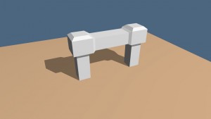
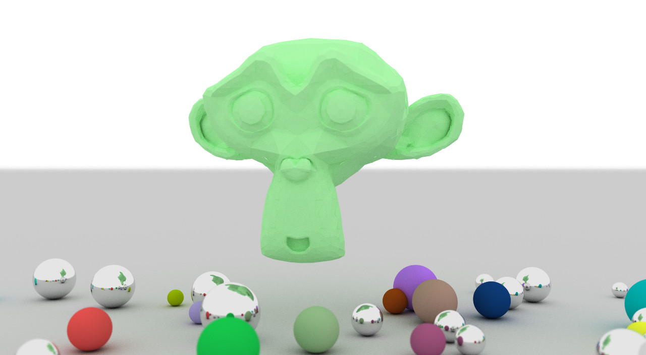
We will continue with the project we left off with in this post. We will attempt to add triangles to our list of primitives. Once we are able to render triangles, this opens the door to rendering full scale models. However, because models will contain upwards of thousands of triangles, we need to be able to organize those primitives effectively for intersection tests. For this we have implemented a rudimentary binary space partitioning. We will discuss towards the end what could be done to improve efficiency. Below are two renders.


In the post, A calibration method based on barycentric coordinates for multi-touch systems, we discussed barycentric coordinates. That concept will be used here for our triangle intersection tests. Our first job is to locate the point, \(\vec{p}\), where the ray intersects the plane in which the triangle lies (this was discussed a bit here). If a triangle is defined by the vertices, \(\vec{p}_0\), \(\vec{p}_1\), and \(\vec{p}_2\), the triangle normal can be given as \(\vec{n} = (\vec{p}_1-\vec{p}_0)\times(\vec{p}_2-\vec{p}_0)\). Once we have found the point, \(\vec{p}\), we evaluate the barycentric coordinates, \(s\) and \(t\), of the point relative to the triangle. These equations are given below, where \(\vec{v}_0 = \vec{p}_1-\vec{p}_0\) and \(\vec{v}_1 = \vec{p}_2 - \vec{p}_0\).
\begin{align}
s &= \frac{(\vec p \cdot \vec v_0)(\vec v_1 \cdot \vec v_1)-(\vec p \cdot \vec v_1)(\vec v_0 \cdot \vec v_1)}{(\vec v_0 \cdot \vec v_0)(\vec v_1 \cdot \vec v_1)-(\vec v_0 \cdot \vec v_1)^2}\\
t &= \frac{(\vec p \cdot \vec v_1)(\vec v_0 \cdot \vec v_0)-(\vec p \cdot \vec v_0)(\vec v_0 \cdot \vec v_1)}{(\vec v_0 \cdot \vec v_0)(\vec v_1 \cdot \vec v_1)-(\vec v_0 \cdot \vec v_1)^2}
\end{align}
Provided \(s\geq0\), \(t\geq0\), and \(s+t\leq1\), we can conclude that the point, \(\vec{p}\), lies inside the triangle. We can then reflect or transmit the ray appropriately depending on the material type.
This addendum to the path tracer project was relatively straight forward, but it does not scale well. For each ray we must find the nearest intersection, and for \(n\) primitives this amounts to \(n\) intersection tests on each ray bounce. We cannot afford to check each primitive on models containing thousands of primitives, so we have added a basic binary space partitioning.
The partitioning tree is generated host-side and transferred to the device. For this we have elected to represent our tree structure as a structure of arrays. Below is the structure as it stands. depth represents the depth of a specific node, minx, miny, ... maxz represent the bounds of the node, child0 and child1 represent the array index of the two child nodes, parent holds the index of the parent node, id is the index of the node, and leaf_id is a separate indexing that applies only to the leaf nodes. The leaf_id gives us an offset into the objects array which, itself, applies only to the leaf nodes. n_objects applies to all nodes and represents the number of objects that pass through a node. Lastly, max_depth holds the depth of our tree, size is the number of nodes, and leaf_size is the number of leaf nodes.
struct _bounding_box {
	unsigned short *depth,
		       *depth_device;
	double *minx, *miny, *minz, *maxx, *maxy, *maxz,
	       *minx_device, *miny_device, *minz_device, *maxx_device, *maxy_device, *maxz_device;
	short *child0, *child1,
	      *child0_device, *child1_device;
	short *parent,
	      *parent_device;

	short *id, *id_device;
	short *leaf_id, *leaf_id_device;

	unsigned short *n_objects,
		       *n_objects_device;
	unsigned short *objects,
		       *objects_device;
	unsigned short max_depth;
	unsigned short size, leaf_size;
};
If we have a tree with depth 3, then \(\text{size} = 2^{(3+1)}-1 = 15\) and \(\text{child_size} = 2^{3} = 8\). Thus, we would have \(15\) nodes in total and \(8\) leaf nodes.
The idea was to first evaluate (after the camera transformation) the minimum and maximum axes values of the axis-aligned box that bounds every primitive in our scene. These values are passed to our tree-building function, and the tree is generated by splitting along the major axis. If the dimensions of our root node are \((1,2,3)\), we would first split along the \(z\)-axis resulting in two children of size \((1,2,1.5)\). The second splits would occur along the \(y\)-axis resulting in 4 nodes of size \((1,1,1.5)\).
Once we reach a leaf node, we cycle through all of the primitives in our scene seeking those primitives that pass through the leaf node. Once the tree is built and all leaf nodes have been processed, we propagate back the number of objects in each child node to its parent. In the code we have also merged the objects from child nodes to the current node if the number of objects is below a certain threshold. There would be no sense in testing 16 child nodes if they all contain the same primitive.
When testing child nodes for the containment of primitives, we have cheated a bit. For one we have not added any plane primitives to the partitioning. We simply add these primitives to the list of objects we test for intersections. For the sphere primitive we have evaluated the radius of the bounding sphere of the given tree node and compared it with the radius of the primitive. If the distance between the sphere center and the box center is less than the sum of the radii, we include the primitive as passing through the tree node. Consequently, this will include spheres that should not necessarily belong to the node, but it will include all the spheres that should. Lastly, when testing for the containment of triangle primitives in a given tree node, we evaluate the axis-aligned bounding box of the primitive and test for overlap between the two bounding boxes. Again, this will potentially include many more primitives than it should but will capture all that is necessary.
Our ray sampling procedure has been updated to query for intersections with the bounding box. If we find the ray hits the root node, we then query the two child nodes. If the ray hits a child node, we check the children of that child node. We continue like this until we reach a leaf node. Upon reaching a leaf node, we add the objects contained in that leaf node to the list of objects to test against for intersections. Below is the function for testing whether a ray intersects an axis-aligned bounding box. There are a few cases. If the node does not contain any primitives, there is no point in testing any furthur (no children will contain any primitives either). Additionally, the ray could originate inside the bounding box, and, lastly, we check for intersection with the left, right, bottom, top, rear, and front box faces.
__device__ bool rayIntersects_device(_bounding_box& b, unsigned short index, __ray r) {
	// contains objects
	if (b.n_objects_device[index] < 1) return false;

	// containment of ray origin
	if (r.origin.x >= b.minx_device[index] && r.origin.x <= b.maxx_device[index] &&
	    r.origin.y >= b.miny_device[index] && r.origin.y <= b.maxy_device[index] &&
	    r.origin.z >= b.minz_device[index] && r.origin.z <= b.maxz_device[index])
		return true;

	// intsection tests
	if (r.origin.x < b.minx_device[index] && r.direction.x > 0) { // check left face intersection
		double t = (-b.minx_device[index] + r.origin.x) / -r.direction.x;
		//double x = r.origin.x + t * r.direction.x;
		double y = r.origin.y + t * r.direction.y;
		double z = r.origin.z + t * r.direction.z;
		if (y >= b.miny_device[index] && y <= b.maxy_device[index] && z >= b.minz_device[index] && z <= b.maxz_device[index]) return true;
	}
	if (r.origin.x > b.maxx_device[index] && r.direction.x < 0) { // check right face intersection
		double t = (b.maxx_device[index] - r.origin.x) / r.direction.x;
		//double x = r.origin.x + t * r.direction.x;
		double y = r.origin.y + t * r.direction.y;
		double z = r.origin.z + t * r.direction.z;
		if (y >= b.miny_device[index] && y <= b.maxy_device[index] && z >= b.minz_device[index] && z <= b.maxz_device[index]) return true;
	}
	if (r.origin.y < b.miny_device[index] && r.direction.y > 0) { // check bottom face intersection
		double t = (-b.miny_device[index] + r.origin.y) / -r.direction.y;
		double x = r.origin.x + t * r.direction.x;
		//double y = r.origin.y + t * r.direction.y;
		double z = r.origin.z + t * r.direction.z;
		if (x >= b.minx_device[index] && x <= b.maxx_device[index] && z >= b.minz_device[index] && z <= b.maxz_device[index]) return true;
	}
	if (r.origin.y > b.maxy_device[index] && r.direction.y < 0) { // check top face intersection
		double t = (b.maxy_device[index] - r.origin.y) / r.direction.y;
		double x = r.origin.x + t * r.direction.x;
		//double y = r.origin.y + t * r.direction.y;
		double z = r.origin.z + t * r.direction.z;
		if (x >= b.minx_device[index] && x <= b.maxx_device[index] && z >= b.minz_device[index] && z <= b.maxz_device[index]) return true;
	}
	if (r.origin.z < b.minz_device[index] && r.direction.z > 0) { // check rear face intersection
		double t = (-b.minz_device[index] + r.origin.z) / -r.direction.z;
		double x = r.origin.x + t * r.direction.x;
		double y = r.origin.y + t * r.direction.y;
		//double z = r.origin.z + t * r.direction.z;
		if (x >= b.minx_device[index] && x <= b.maxx_device[index] && y >= b.miny_device[index] && y <= b.maxy_device[index]) return true;
	}
	if (r.origin.z > b.maxz_device[index] && r.direction.z < 0) { // check front face intersection
		double t = (b.maxz_device[index] - r.origin.z) / r.direction.z;
		double x = r.origin.x + t * r.direction.x;
		double y = r.origin.y + t * r.direction.y;
		//double z = r.origin.z + t * r.direction.z;
		if (x >= b.minx_device[index] && x <= b.maxx_device[index] && y >= b.miny_device[index] && y <= b.maxy_device[index]) return true;
	}

	// no intersection
	return false;
}
Below is the function that adds primitives to the hit list. These are primitives we must check directly for intersections. It was an attempt to avoid recursion and is fairly crude. It starts by testing the root node and continues to add indices on a bounding box hit. When a leaf node is reached, we add only those primitives that have not already been added.
__device__ short intersects_device(_bounding_box& b, int i, __ray r, short hit_list[]) {
	int index = 0,
	    count = 1,
	    indices[30000];
	indices[index] = 0;

	short hit_count = 0;
	bool found = false;

	while (index < count && index < 30000) {
		i = indices[index++];
		if (rayIntersects_device(b, i, r)) {
			if (b.depth_device[i] == b.max_depth) {
				for (int j = 0; j < b.n_objects_device[i]; j++) {

					short hit = b.objects_device[ b.leaf_id_device[i] * 10000 + j ];

					found = false;
					for (int l = 0; l < hit_count; l++) {
						if (hit_list[l] == hit) {
							found = true;
							break;
						}
				    }

				    if (!found) hit_list[hit_count++] = hit;
				}
			} else {
				indices[count++] = b.child0_device[i];
				indices[count++] = b.child1_device[i];
			}
		}
	};

	return hit_count;
}
The sampleRay function has been updated to use the intersects_device method. It now loops over only those primitives that should be tested directly. Since we are handling planes directly, the project expects those planes to be added to the objects list first. The sampleRay has a second loop for handling planes. Once a primitive other than a plane is found, it breaks from the loop.
Occasionally during testing, the kernel would timeout. The number of rays each kernel call is forced to handle has been reduced to help prevent this from occurring. A kernel call now handles a 2 by 2 grid of blocks sized 16 by 16. Thus, at the moment the kernel only handles 1024 pixels on each pass. We send an offset in both the \(x\) and \(y\)-directions to update the entire image over successive loops.
Blender was used to export 3D models in OBJ format. The project expects triangles and normals to be present in the OBJ file. When exporting do not forget to check "Include Normals" and "Triangulate Faces".
This project is fairly crude. Below is a list of some ideas that could be implemented to improve the efficiency of the project.
- kd-tree
- improved intersection testing
- ray-triangle intersections
- containment testing for spheres in nodes
- containment testing for triangles in nodes
- shared memory
- generating tree structure on device
Have a look at the project, and let me know if you have any questions or suggestions.
Download this project: pathtracer_dof_triangles.tar.bz2