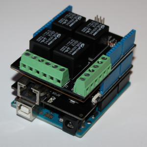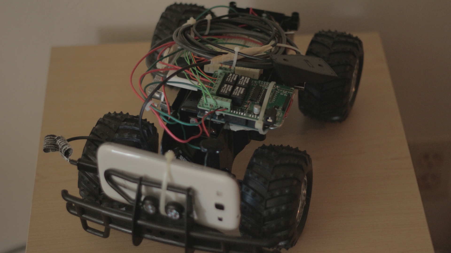
The purpose of this project was to create an internet-based rover using the combination of a cheap RC vehicle, an Arduino Uno with a Seeed Relay Shield, a Samsung Galaxy S3 in host mode, a workstation and PlayStation 3 controller. Our server software will run in the background on the S3 and visual feedback will be provided by the IP Webcam app available on Google Play. The client software will run on the workstation and send the status of the PlayStation 3 controller to the S3. The S3 will in turn communicate the status to the Arduino via USB. The relay shield will control the motor and servo on the RC vehicle.
Below are a couple photographs of the rover.


To install the Arduino IDE on the Debian distribution run,
# apt-get install arduino
Below is the sketch for the Arduino board. The board receives communication from the S3 and decodes it. The relays are activated by taking pins 4 through 7 high. The board might receive the byte, 01100000b, which would take relays two and three high. We have the rover connected to the relay shield such that this would correspond to an orientation of the current resulting in a forward-right motion.
void setup() {
  Serial.begin(9600);
  for (int i = 4; i <= 7; i++) {
    pinMode(i, OUTPUT);
    digitalWrite(i, HIGH);
  }
}

void loop() {
  bool states[8];
  bool bytes_read = false;

  while (Serial.available() > 0) {
    int j = Serial.read();
    for (int i = 0; i < 8; i++) {
       states[i] = (j>>i)&1;
    }
    bytes_read = true;
  }

  // pin 4 - relay 1 - forward
  // pin 5 - relay 2 - right
  // pin 6 - relay 3 - reverse
  // pin 7 - relay 4 - left
  if (bytes_read) {
    for (int i = 4; i <= 7; i++) {
      digitalWrite(i, states[i-4] ? HIGH : LOW);
    }
  }
}
The following schematic can be found here at the Velleman forum. This is sufficient to control the drive motor, but we need a second setup for the servo.

We have connected the leads from the drive motor to COM1 and COM3 on the relay shield. NC1 and NC3 are both connected to a positive voltage source. NO1 and NO3 are connected to ground. The relay shield also needs a 9 volt source to activate the relays. We connected a 9 volt battery plug to +9V and GND. The servo motor is handled similarly on relays two and four.
The S3 needs a USB On-The-Go cable to activate host mode. If you do not have an On-The-Go cable, you can hack one fairly easily. We spliced a male Micro USB connector with a female connector and shorted pins 4 and 5 on the Micro USB connector. We used a thin piece of magnet wire, burned off the enamel, folded it in to a U-shape, and stuck it against pins 4 and 5. When you plug it in to the S3, the mobile should say, "USB connector connected."
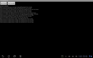
For the server software we modified this project to add USB support. The USB vendor id and product id for this board is 9025 and 67, respectively. The Arduino board has two interfaces and two endpoints on the second interface. We will send data to the board on the first endpoint of the second interface. Rather than paste the source code here, it is available in the project download. See ThreadedServerArduinoController.java. If you have any questions about it, let me know. Briefly, the Android software sets up a server thread ready to spawn child threads on incoming connections. When you click "Enumerate Devices", it sets up a USB thread. When a client sends a string, the child process decodes it and prepares it for sending to the Arduino board. The USB thread sends the data (when the button states have changed) to the Arduino board.
The rover itself should be complete at this point, all that is left is a discussion on the client app.
The client software is available in the download under threaded_server_arduino_controller_client. This is a basic client app which includes the code from the joystick project. With the server running on port 31236 on the S3 and the client compiled and linked, you can connect to the S3 from the client via the following command,
# bin/main [s3 ip address] 31236
Lastly, with the server running in the background on the S3, you can start up the IP Webcam server and connect to it from your workstation via VLC or browser.
Let me know if I can clarify anything or if you have any comments.
Download this project: rover_project.tar.bz2